After a bumpy return to the track at Winton I have returned, experiencing a very wet Broadford and perfect Winton.
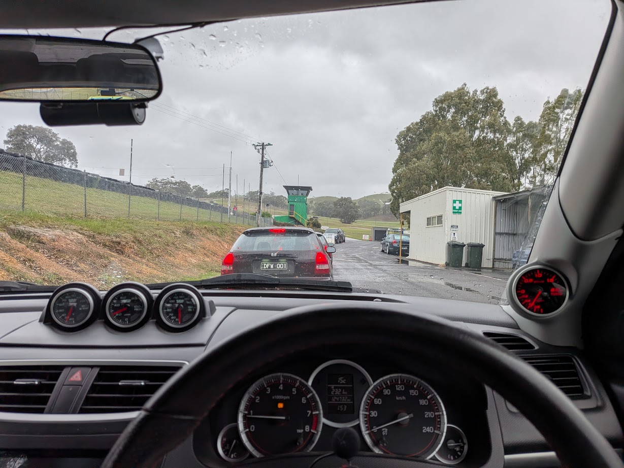
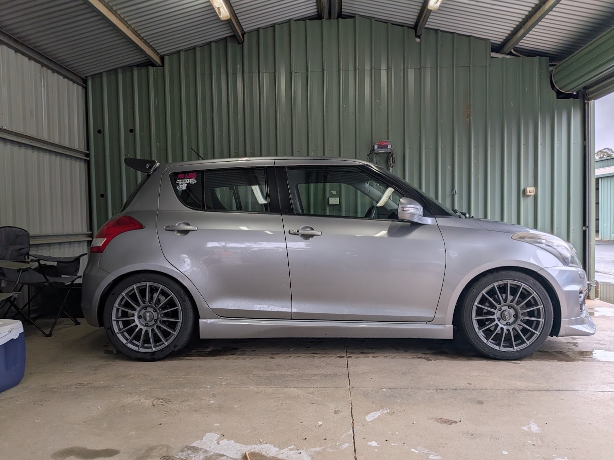
I have volunteered as a flag marshal at Broadford a few times, both times were cold and wet, this time was no different. Due to the miserable conditions, I left my street wheels on and took it easy, using it as another chance to shakedown the car and do some logging.
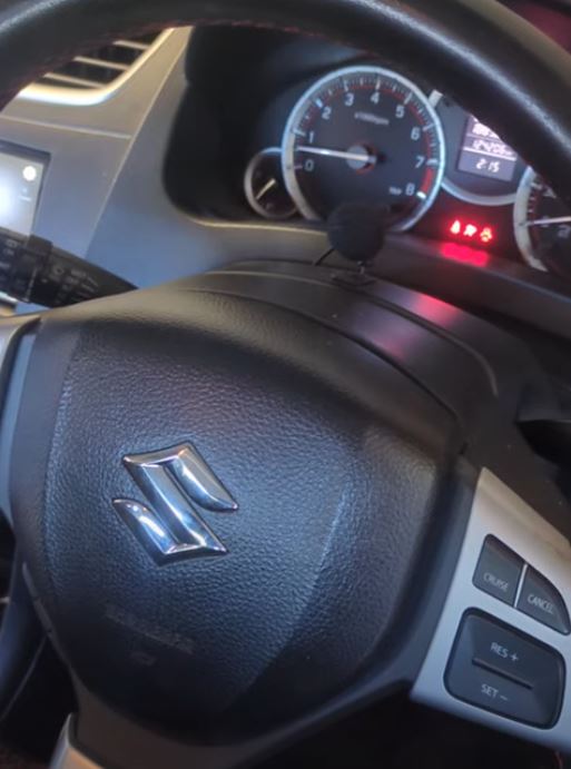
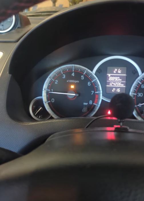
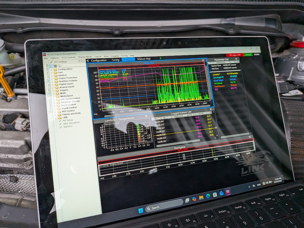
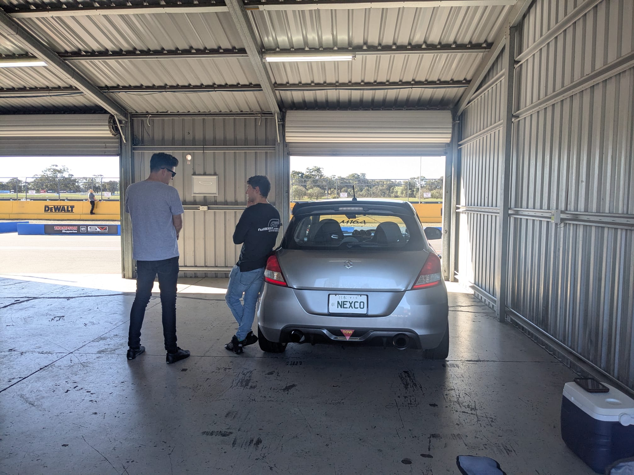
Setting up logging through the Link wasn’t that intuitive, however once I had all the parameters selected, downloading and viewing the data was a breeze. Throughout the day there was nothing of concern, a boost referenced FPR would be a good idea should I upgrade the turbo. Additionally, upgrading the ECU and adding DBW would help a lot as the factory throttle is not particularly happy during downshifts.
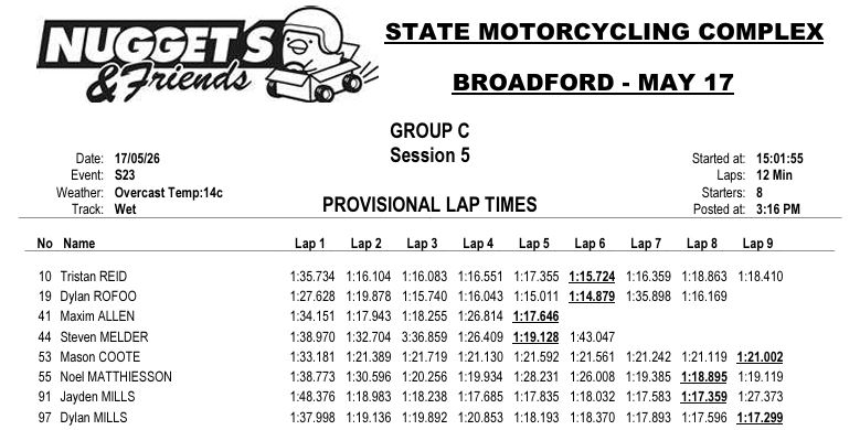
A default [wet] PB of 1:17.6 was achieved on RE003s.
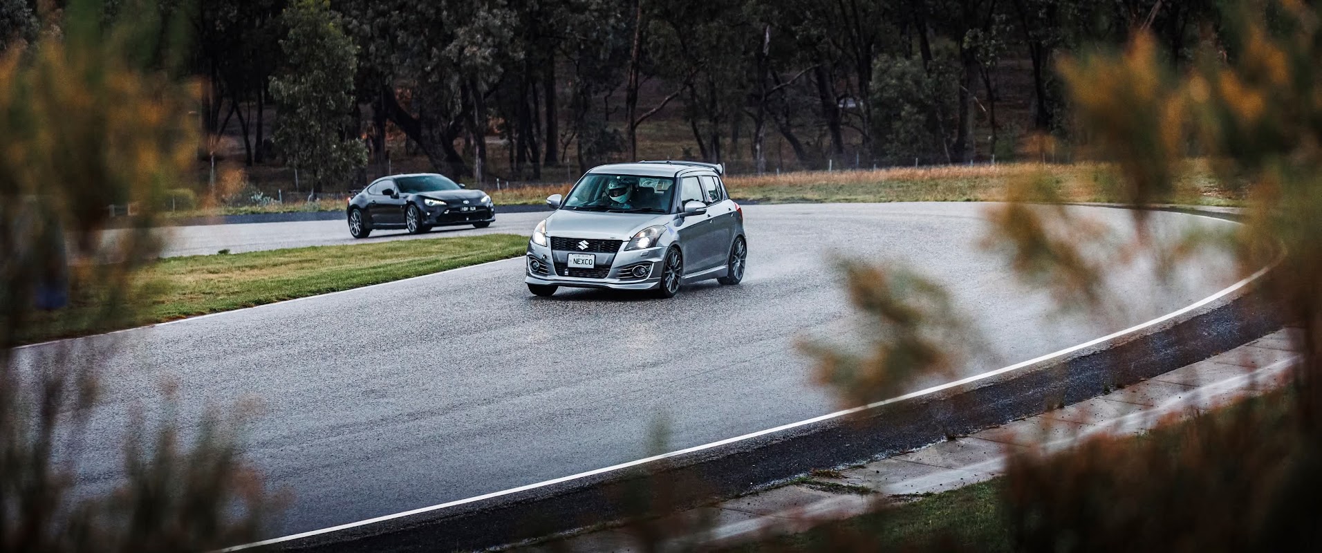
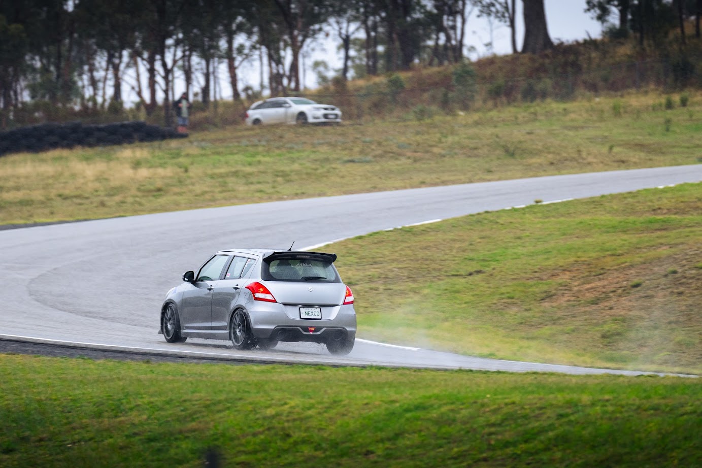
Photo Credit: Shaun Tanner [LHS], Jason Ngo [RHS]
Only 5 days later I attended a Test & Tune at Winton. The weather was perfect and I was keen to build my confidence back up, continuing to work on my heel-toe.
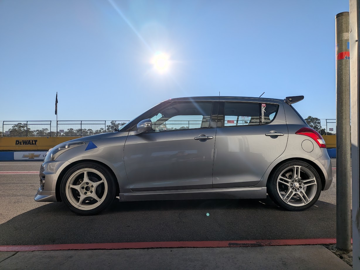
I barely improved on my last outing however I felt like I drove a lot better. Comparing data against my NA PB was interesting. I lose a lot of time between T3 and the exit of the sweeper, about 2s and then gain it all back over the remainder of the lap. The sweeper in particular is proving problematic, I do not feel like the grip is there to maintain the speed I had when NA, this is likely due to a mix of myself and the downgrade in tyres, running an AD09 now compared to RE-71R.
I ended the day with a 1:44.37 with an optimal that was close to my NA PB but lower than the optimal from my last time out 🙁
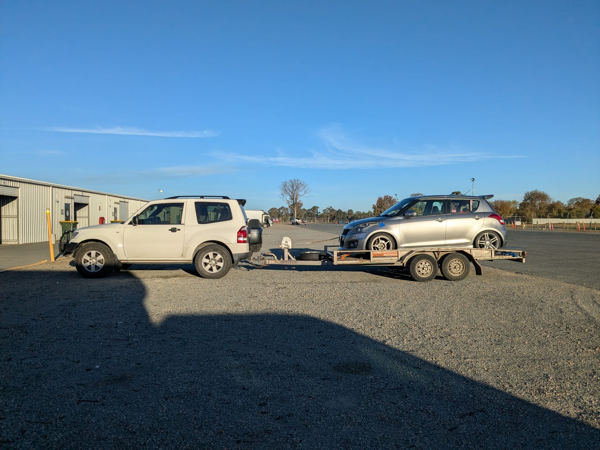
Keen to get back out on track and continuing the momentum I have going now. On a side note, the Pajero shorty towed excellently, averaging 13.5L/100km over about 500kms between Winton & home. The U-HAUL trailer we rented was a bit of a dud, Move Yourself dovetail trailers are far superior, lessons learned.
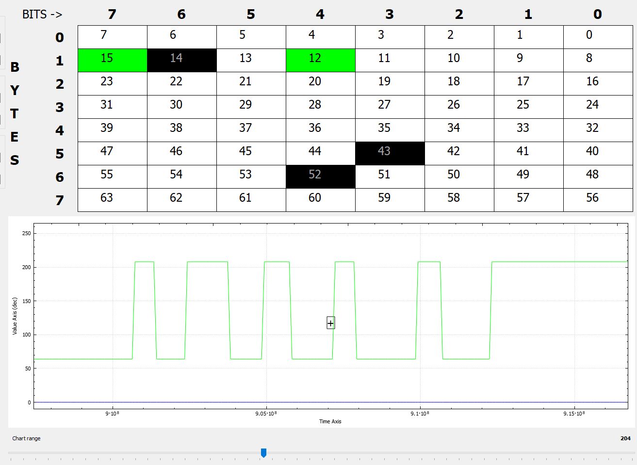
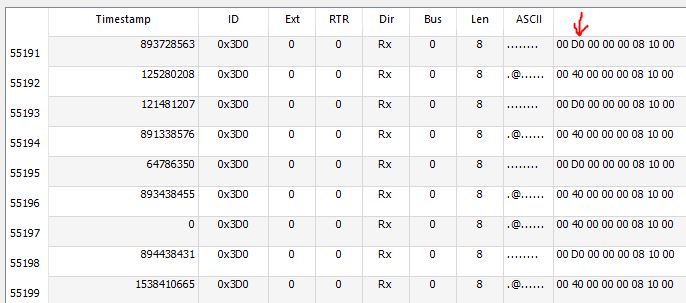
I am also still searching for a stock, manual ZC32S to close out my CANBUS troubleshooting…